
Purpose of the
discontinuity of the material and dimensions of the non-destructive testing is
to detect it without destroying the material. Sizes and types of
discontinuities compared with the standards. Discontinuities in excess of permissible
limits that are considered errors, material is sent for repairs or is rejected.
In this way, errors are detected clearly and it gives get rid of cost of
destructive testing and necessary labor. In daily life people uses transportation
vehicles, communication products, home stuffs, hand tools etc. For all these
instruments some metallic and non-metallic materials are used. Using for these
instruments, materials which are used in them should be tested many times
clearly. Wide range of uses these materials directly affect the testing method
which is non-destructive testing.
Why do you need to non-destructive testing?
- Prevention of Accidents
- Improvement of product reliability
- Determination of the adequacy
- Provide sufficient information on an issue
For this reason, the following elements are required in order to obtain the information;
- Trained and qualified personnel
- The application procedure of test
- A system for reporting results
- A standard for interpretation of results
Commonly Used 6 Main NDT Methods
- Liquid penetrant inspection
- Testing with magnetic particles
- Eddy Current Inspection
- Ultrasonic Inspection
- Radiographic Inspection
- Inspection with eye or optical instruments
Liquid Penetrant Inspection
Liquid penetrant testing is a
non-destructive testing that is used for detecting the capillarity or surface
discontinuities which is based on capillary affect. In the liquid penetrant
inspection, liquid is applied on surface of sample and waiting for the liquid
reaches in surface discontinuities.


After the enough time which liquid penetrant will be reach into the
capillary area, the surface of sample is cleaned. For to draw the liquid
penetrant on discontinuity ,capillary affect also used as an absorbent. In any
case which blocking the liquid to entering the discontinuities of the penetrant
should be removed.
Discontinuous regions on the surface can be covered with silly or sand
blasting method.

The steps of liquid penetrant test will be explained using paintings
below.

A. Applied to the surface penetrant
B. Time allowed leaking the penetrant into open areas
C. Clean the more penetrant on surface
D. The developer is applied on surface to take on the penetrant from
open areas
E. The sample under visual inspection
F. Last cleaning
Penetrant Test Equipment
Depending on the process and type, following features are should be on
stable penetrant test equipment.
- Cleaning station
- Penetrant station
(tank)
- Unloading station
(tank)
- The emulsification
station (tank)
- Agitation station
(tank)
- Developer station
(tank)
- Dryer station (tank)
- Inspection station (Using black light)
-
Last
cleaning station (Far from the penetrant station)

Almost every liquid can named as penetrant. However easy cleaning,
spreading homogeneously, carrying the color easily type features gives
preferable property to liquid which want to be use as a penetrant.
Another important point is temperature of penetrant or temperature of
sample can affect time required for penetration. Therefore, heating the sample
up to 70 Fahrenheit or more temperature will accelerate the penetration.
Testing with Magnetic Particles
Certain metals to be able to magnetization, using an agent which has magnetic
attraction property like iron powder can uncover possible discontinuities. Magnetic particles, during or after the induction of the magnetic field
is applied to the surface of the test sample.
Following figure shows, the structure of magnetic particle have active
article on discontinuities which is on magnetized sample.

Magnetic particle testing is an easy and simple testing for magnetic
materials and it can applied during the every steps of process and
manufacturing.
The aim is to ensure the reliability of the magnetic particle test
items by the following ways:
- To obtain a finding of
a visual image of a material surface
- To determine the
structure of discontinuities without damaging the material
- Distinguish to acceptable
and unacceptable materials according to the predetermined standard
An object, the magnetic field all or a portion magnetized when placed
north and south poles as shown in the figure below.

Pole is called to pull or push capability of the local focus of a
magnet. North and South poles show pulling or pushing
characterized as shown below.

Magnetic power lines form a closed loop and these lines cannot
interrupt each other. All of these power lines create magnetic field. Magnetic
power lines and own magnetic field are shown in following figure.

Other magnetized material is provided to attracting force to the magnetic poles named as magnetic flux. This flux forms from all magnetic power lines.

In angular magnets magnetic field consist
totally inside of angular shape. Changing cracks disrupts the flow of lines of
force within an annular magnet and forms a flux leakage.

In real, flux leakages are a magnetic power line which leave the
angular magnet and travels the one pole to another in air. When the stray field
exposed to a force so as to get out of the track, iron particles is arranged so
as to show a sign of discontinuities.
If the leakage field strong enough, as shown below, it can be
determined even subsurface discontinuities.

Some magnetic materials:
- Diamagnetic metals: Magnetic
sensitivity negative and small. For example, copper, silver and gold.
- Paramagnetic metals: Magnetic
sensitivity is positive and small. For example, magnesium, molybdenum,
lithium and tantalum.
- Ferromagnetic metals:
Gravitational force is very large, and even retains the magnetization
magnetic field is removed. Iron, cobalt and nickel are an example
ferromagnetic material.
Eddy Current Inspection
Eddy current is a suitable method for the detection of surface defects.
Method can be applied to all electrically conductive metals and alloys. However,
it is more effective in the non-ferromagnetic material.
The
principle of the variable magnetic field generated by an alternating current
coil, the circular surface of the material is based on the induction of eddy
currents. This induced eddy current constitutes a second magnetic field in the
opposite direction to the magnetic field in the coil. If there is a
discontinuity in the region of formation of eddy currents in the test piece due
to the difference in electrical resistance between the test material and
transient current will follow a different trajectory. This difference is
detected by the coil.

Eddy current test
is applied in the following purposes different from error testing:
•
Coating
thickness measurement
•
Electrical
conductivity measurement
•
Classification
of metals according to their chemical composition
Within acceptable
limits over the entire surface of the material thickness are tested to
determine whether there is a thin layer of aluminum. In this case the coil is
placed on a bridge offset by the correct standard. Operators of the same type
of aluminum and upper and lower limits acceptable according to what standards
should ensure that rolled.

Eddy current
inspection coils are designed according to specific application areas. So far
the material surface or control coils placed near the coil was known until now.
Which are :
- Surface coil
- Peripheral coil
- Inner coil
The coil is used
as a wear-mounted probe tip over a surface it has epoxy coating. The coil spring
supported in a housing can be mounted. The spring continuously tested by
preventing the detachment of the coil allows applying a constant pressure. Slots
may be designed to fit the geometry of the material being tested in other
words, to meet any particular requirement. Thus surface probe, can be in an
unlimited number of different ways. given all the coils belonging to this class
is known as surface coils.

Eddy Current Orientation

A seam discontinuity in the
structure of the test piece surface coils can be used to detect the presence
and location of the seam. According to permanently bar to reveal cracks in the surface
coil circular bar-shaped test pieces need to remain on the same geometric
position. In this case, so that the same radius in the bar will require a
curved equipment layout.
Coil Shape and Sizes
Control coils, are produced in various sizes and shapes. Coil diameter
is one of the major factors that contributed to the discovery of the
discontinuity. For best results, a smaller diameter and a shorter
circumferential surface coils and the inner coils are obtained when used, but
such coils, which may be more susceptible to changes in lift-off and filling
factor.
A long coil and then the best sensitivity for detecting longitudinal
cracks is controlled with a short coil will be obtained when the cut off a
large portion of the vortex flow created fractures.
Depth of Penetration
Eddy processing inside of another dimensional eddy current in the
current control factors is depth. Magnetic field of the coil surface will fully
penetrate the thick test pieces. Weight limits and possible factors that
influence the penetration depth is available. Eddy currents are
not distributed and properly controlled on a test piece. Located just below the
surface of the coil intense eddy currents, right below the surface, it
decreases in inverse proportion to the increase in the distance.

When electrical resistivity and relative permeability are known.

d
|
=
|
Standard Depth of Penetration (mm or inch)
|
r
|
=
|
Electrical Resistivity(mohm-cm)
|
f
|
=
|
Test Frequency (Hz)
|
mr
|
=
|
Relative Magnetic Permeability (dimensionless)
|
Ultrasonic inspection
All errors with ultrasonically tested within accuracy limits. Errors
are detected when they are in the best shape in the direction perpendicular to
the ultrasonic beam. Coarse-grained structures are particularly difficult
Ultrasonic testing of austenitic materials
Material is sent to ultrasonic vibrations called vibrations. It
described the backscatter the sound vibrations and must be interpreted. Answers
desired properties it does not provide any material to be used in other methods
of Non-Destructive Testing
Vibrations, many examples given environment; the fingers touched the
sound of a radio cab moment felt a sensation in the fingers. This means that
the energy is detected. Two facts should be noted that about vibrations as fit
for purpose. These are ;
- Vibration forwards and
backwards,
- Energy is a form of
vibrational motion.

Pass through the material of the ultrasonic vibration, it is related to
the material elasticity. Elasticity enables the ultrasonic waves pass through
the material energy. "Vibrations" movement is now known, each one of
these movements "cycle" is called. When applied blow to the metal
surface, interior surface toward collapse. The inner surface of the distance
toward the collapsed portion of "displacement" is called. Two
displacement creates a cycle. Metal, because it has the elasticity back down
the surface so the original (static) position is the future. Surface is the
right way to take the maximum from the move and in the opposite direction from
its original position. The maximum distance from the "displacement"
is called. As a result, the surface again returns to its center position or
stagnant. so that the sequence of all the action "cycle" is determined.

Shaking the globe continues in different numbers. consisting completed
within the given time limit cycle 's total number of "frequency" is
called. The only time measure used sec. Thus, in the case of a second cycle,
"cycles per second" are accepted. Unit as a term used universally
accepted and frequency measurement "Hertz" (Hz) are used.
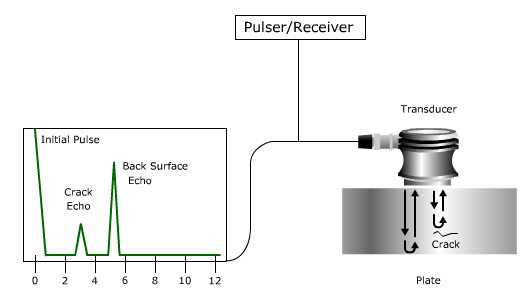
Transducer will collect its response to the ultrasonic vibration material.
The energy may also be pulsed or continuously sent by the transducer. Sometimes
a transducer energy, material in a very short period of time (micro seconds)
transmits energy and creates space, pausing briefly before taking it again.
This is called "pulsed sound" and there was no vibration
before and after the short pulse group is treated as other groups.
Radiographic Inspection
Test records permanently and widely applied the method to be highly
sensitive radiography.
The test piece is irradiated with a radiation beam emanating from a
source. It reaches the film disposed on the rear surface of the part after the
radiation passes through the material.
In order to be absorb different radiation intensity of the radiation
passing through the region by discontinuities where the blackout will create
discontinuities and will be different in the film. After the film's bath
process becomes seen as a symptom of errors tarnish on the film. It can be
detected with radiography methods as long as they are planar defects parallel
to the radiation beam.

X-ray film evaluation room light intensity should be 20Lux( 2 Foot
candle)
Inspection
with eye or optical instruments
(Visual inspection)
(Visual inspection)
Visual examination of surface discontinuities light control used in
quick, cheap, simple and oldest non-destructive testing methods. cracks can be
visibly accessible surface open sections of the piece to be controlled and
monitored by this method in terms of the general structural discontinuities
such as corrosion is checked.

Noticeably reach
the surface to be checked in the inspection, cleaning of the surface, so that
it must be large enough to be seen from error are factors that limit this
examination. Eye examination in a good light source, available aids such as a
magnifying glass and mirrors. Opinion opportunities in areas that are difficult
to spot the type of light source used. What eyes where you see one of the most
important elements of such an examination is obliged to identify
discontinuities that good looking.
Eye examinations
are performed using optical instruments in other matters will be examined
within the scope of the examination. Discontinuities in small enough to be
invisible to the human eye baroscope endoscope and made visible to the human
eye level with the use of optical instruments such as microscopes and thereby
control the presence of the discontinuity.

Shape of baroscope
According to the
location of the property to be controlled are used in many types of borescopes.
Some of these fixed some flexible structure, which can be extended in length,
illuminated in various ways (right angled left angled, angled backward) and may
be listed as fiber optic baroscope. If the combustion chambers of aircraft
engines will use examples to place the turbine and compressor control panel and
the inside of the cylinder.

Borescope and be
seen with the naked eye as small discontinuities micro-optical comparator can
be 5 to 500 times larger object and can be identified by the use of a microscope.
Microscope examination of the grain structure of the material, cracks formed in
the micro-level, and monitored the progress of the cracks and can be examined.

Eye examination is seen illuminated magnifying glass used in the
application help. Additionally cavities, holes and various recesses of the
pieces are inaccessible or invisible places of examination purpos shows a
flexible fiber optic cable baroscope equipment. This type of display device can
be transferred to the screen via a camera and can display photos taken or
modified on.
Of course, today, thanks to increased use of advanced technological
means and image processing techniques to use for this purpose and finger
miniature camera.
I haven’t known about it before. This article is very helpful!
ReplyDeleteThank you so much!
Eddy Current testing in UAE
I read your blog on a daily basis. This is a really great and informative post. Thanks for sharing.
ReplyDeleteNon-Destructive Testing Instruments
Thanks for this post. Service Provider of Eddy Current Testing in UAE Service offered by EIWAA Group, Sharjah, UAE.
ReplyDeleteEddy Current Testing
Eddy Current Testing in Dubai
Thanks for this post. Service Provider of Eddy Current Testing in UAE Service offered by EIWAA Group, Sharjah, UAE. Eddy Current testing or Eddy Current Inspection is used for the detection of surface breaking/cracks and near surface planar defects in welds, heat affected zone and parent material. EIWAA offers eddy current testing applied on coated and uncoated objects &the eddy current testing can be carried out on all accessible surfaces on welds of almost any configuration. Minimum Surface preparations is required for the eddy current testing. Depending on the sensitivity requirements, Eddy current inspection is able to detect surface cracks through non metallic coating of up to 2mm thickness.
ReplyDeleteEddy Current Testing
Tank Calibration Services
Pipe Freezing Services
For More details visit our website: https://eiwaagroup.com/bollard-load-testing-companies-uae/
Eddy Current Testing is a non-destructive testing (NDT) inspection method used for a variety of purposes, including for flaw detection, material and coating thickness measurements, material identification and establishing the heat treatment condition of certain materials.
ReplyDeleteEIWAA, Leading NDT Inspection Companies in UAE using both Conventional NDT Inspection technique as well as Advanced NDT Inspection methods. Our Eddy Current Inspection system accompanied by special probes are typically used to obtain higher test sensitivity for non-magnetic conductive materials.Storage tank survey
ADNOC Approved<a href="https://eiwaagroup.com/welder-and-brazing-quality-test-uae/”> Welder Qualification Test
Brazing Operator Qualification Test </a>
Thanks for this post...Eddy Current Testing is a non-destructive method for testing metal surfaces for defects such as cracks or discontinuities. Such surface defects have high-frequency electromagnetic interactions that allow them to be detected manually or automatically, depending on the requirement, and evaluated.
ReplyDeleteTank Calibration Services
Water bag rental in Saudi
Pipe Freezing Services
Thanks for such an useful and informative article. One Stop NDT is an informative dais for anyone who is an NDT enthusiasts. Backed by professionals with unprecedented experience & presence of more than 20 years in NDT Market, One Stop NDT gives you a chance to freely communicate and interact with experts.
ReplyDeleteIn addition to our professional services, Industrial-NDT also provides equipment for the non-destructive testing of materials to ensure the safety and integrity of your products.
ReplyDeleteNice Post!!
ReplyDeletePlease look here at EWP Annual Inspections Western Australia